

Table of Contents
How to Choose the Best Linear Cross-Belt Sorter for Your Warehouse in India?
The Inflection Point: When Your Current System Stops Being a Solution
There is a specific moment in a warehouse’s operational life when the existing sortation architecture stops being a capacity problem and starts being a structural one.
For narrow-belt sorters and pop-up wheel diverters, that moment typically arrives somewhere between 5,000 and 9,000* parcels per hour. (* Rough estimate. Depends on different factors)
The geometry of these systems—fixed divert points, limited destination counts, and a discharge mechanism that depends on friction rather than positive mechanical force—creates a compounding failure mode at high velocity.
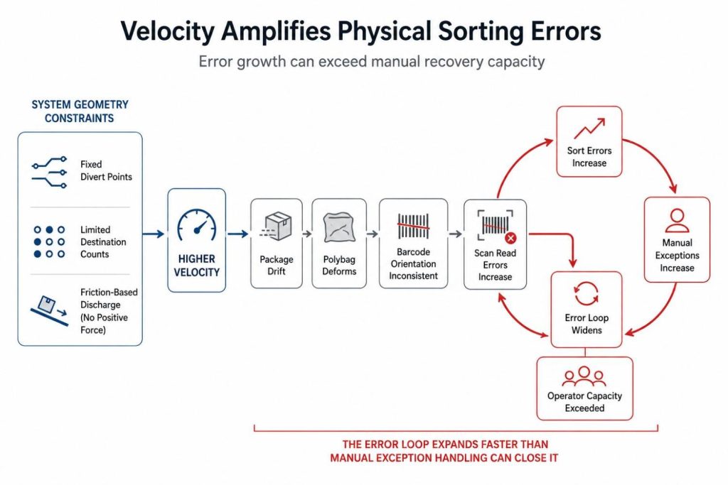
Packages drift. Polybags deform. Barcode orientation at the scan tunnel becomes inconsistent. The error loop widens faster than manual exception handling can close it.
For manual sortation, the ceiling is lower and more unpredictable. It is not a throughput number; it is a cognitive load number.
Somewhere above 1,000 parcels per hour, the combination of hub code misreads, operator fatigue, and physical travel time between induction and deposit creates a mis-sort rate that no staffing increase can linearly resolve.
The linear cross-belt sorter enters the conversation at exactly this point.
At sustained throughput requirements of 8,000 to 15,000* parcels per hour, with mixed packaging profiles, multi-carrier manifests, and hard dock-close windows, it is the only sortation architecture that addresses the problem mechanically rather than operationally. (* Rough estimate. Depends on different factors)
This guide is built for the operations manager, logistics director, or supply chain automation lead who is evaluating that transition. Not the concept of it, the engineering reality of it.
The Core Decision Engineering Framework
1.1 Load Profile Dynamics: What Your Packaging Mix Actually Demands
The first mistake most design teams make is specifying a sorter against an average parcel profile. The system doesn’t run on averages.
It runs on the worst-case parcel in the worst-case orientation at peak throughput velocity.
A linear cross-belt sorter’s carrier unit, the individual cell on which each parcel travels, interacts with the load through a combination of belt friction, gravity, and controlled discharge velocity.
Understanding this interaction is the starting point of any honest system specification.
Rigid cartons (standard dimensional boxes) are the system’s native load. They present consistent contact surfaces, predictable weight distribution, and stable scan orientations.
A well-tuned carrier pitch-belt speed combination handles these with near-zero discharge error.
Polybags and flimsy flats are where the engineering challenge lives.
A polybag with no structural rigidity deforms under its own weight when placed on a carrier belt, shifting the centre of gravity unpredictably.
At high belt speeds, sorter speeds up to roughly 2.5 metres per second are typically the practical ceiling for parcel applications, beyond which lighter items risk becoming airborne during acceleration, and an uncontrolled polybag can slide within its carrier zone before the discharge sequence initiates.
This is not a sorting error in the traditional sense.
The barcode was read correctly. The routing logic executed correctly. The parcel landed in the wrong chute because the physics of a flimsy substrate on a moving belt were not accounted for in the system design.
The mitigation is positive mechanical discharge, a cross-belt mechanism where the carrier belt actively transfers the parcel laterally rather than relying on momentum or gravity alone.
When specifying your system, ask for documented test data specifically for polybag handling, not just the rated PPH figure.
Non-machinable parcels (NMPs), oversized items, cylindrical and irregularly shaped packages require a separate induction protocol.
Most linear cross-belt configurations include a designated NMP bypass lane or manual exception station upstream of the automated induction zone.
The system’s WCS (Warehouse Control System) should flag these before they reach the carrier, not after.
Weight range matters for carrier belt motor sizing. Standard commercial carriers are rated for loads between 50 grams and 50 kilograms.
But the motor torque profile at the lower end of that range, particularly for sub-100g flyers and padded envelopes, requires specific tuning to prevent the carrier belt from over-accelerating the item during discharge.
This is a detail that becomes relevant when your SKU mix includes a high proportion of e-commerce flyers and document envelopes.
1.2 Layout and Footprint Efficiency: Linear vs. Loop in Constrained Spaces
The geometry of a linear cross-belt sorter is its most immediate practical advantage over loop configurations in constrained warehouse environments.
A loop cross-belt sorter requires a closed oval or circular track.
The loop turns, typically with a minimum radius of 2.5 to 4 metres depending on carrier pitch, consume floor area that contributes nothing to sort throughput.
In a warehouse with column grids, mezzanine structures, or irregular floor plans, those turns frequently collide with structural constraints that require either facility modification or significant layout compromise.
A linear cross-belt sorter runs on a straight track.
The entire length of the system is productive sortation length.
Discharge chutes can be positioned on one or both sides of the track, doubling the sort destination count without increasing the system’s footprint.
Measure these things before specifying:
- Clear floor length available for the sorter track (minimum 20 metres for a viable linear configuration; 35–60 metres for high-destination count systems)
- Column spacing and any obstructions within the planned track corridor
- Induction zone clearance at the entry point, typically 4–6 metres upstream of the first carrier to accommodate the scan tunnel, weigh bridge, and label read station.
- Chute depth on each side; discharge chutes require 1.2 to 2 metres of clear space laterally, plus a collection area behind them
1.3 Induction Speed vs. Carrier Pitch: The Matching Problem
This is the most technically underspecified aspect of cross-belt sorter design, and it is the one most likely to result in a system that underperforms against its rated PPH.
Carrier pitch refers to the centre-to-centre distance between individual carrier units on the sorter track.
Standard configurations run at carrier pitches of 600 mm, 750 mm, or 900mm, depending on the maximum parcel length the system is designed to handle.
Induction speed, whether from a manual operator or an automated gapping conveyor, must be precisely matched to the carrier pitch and track velocity to ensure that each parcel lands on a single carrier without overhanging into the adjacent unit.
An overhanging parcel triggers either a system jam or a forced no-read/no-sort event, both of which interrupt throughput.
The matching calculation is straightforward in theory: at a track speed of 2.0 m/s with a 750mm carrier pitch, the system is presenting a new carrier every 0.375 seconds.
A manual induction operator working at full capacity can sustain a placement rate of approximately one parcel every 1.0–1.5 seconds.
The gap between those two numbers is filled by empty carriers, carriers that pass through the system without a load.
Empty carrier rate is the primary reason real-world throughput diverges from rated PPH.
A system rated at 6,500 PPH assumes near-100% carrier utilisation.
In practice, a manual induction setup with one operator per induction point will achieve 60–75% carrier utilisation under sustained peak load.
To reach 85–90% utilisation, which is where the system begins to deliver against its rated throughput, automated induction with a gapping conveyor and pre-aligner is required.
The specification consequence: when comparing systems on PPH, always ask whether that figure is based on automated or manual induction, and at what carrier utilisation rate.
A system quoted at 6,500 PPH with automated induction and 90% utilisation is a meaningfully different machine from one quoted at 6,500 PPH assuming manual induction at 75% utilisation.
Not sure what carrier utilisation your current setup would actually achieve?
Get a free throughput audit — we’ll estimate your real-world PPH based on your induction method, parcel mix, and floor layout, before you commit to a system spec
What Your Manufacturers are Hiding From You (That is Costing You to Lose Money)
2.1 The Polybag Friction Trap
We touched on polybag behaviour in the load profile section, but the failure mode deserves a more specific engineering treatment because it is the most common cause of post-installation performance complaints in mixed-load sortation environments.
When a polybag is inducted onto a carrier belt, three variables determine whether it discharges correctly: the contact surface area between bag and belt, the coefficient of friction between the two materials, and the lateral acceleration profile of the carrier belt during discharge.
Standard cross-belt carriers use a rubber-compound belt surface designed to maximise friction with rigid substrates.
Against a low-density polyethylene polybag, particularly one that is under-filled or loosely sealed, this friction relationship becomes unpredictable.
The bag can micro-shift during transit, rotating slightly on the carrier surface. When the discharge sequence initiates, the belt accelerates laterally, but the bag’s centre of gravity is no longer aligned with the discharge axis.
The result is a parcel that discharges at an angle, potentially landing on the chute divider rather than cleanly into the target chute.
The engineering mitigation has two components.
- Belt surface texture: A fine-grain or ribbed belt compound increases the effective contact friction against deformable substrates.
- Discharge timing tuning: The WCS can be configured to initiate the carrier belt discharge 15–30 milliseconds earlier than the standard timing profile for parcels flagged as low-density by the upstream weighbridge. This compensates for the delayed momentum transfer in lightweight, deformable items.
Neither of these mitigations is standard out-of-the-box on most systems. They require configuration by an engineer familiar with mixed-load behaviour. When evaluating vendors, ask specifically whether their commissioning process includes polybag discharge calibration as a standard step.
2.2 Maintenance Realities: Direct-Drive vs. Belt-Drive Carrier Mechanisms
The carrier belt mechanism, the small conveyor inside each carrier unit, is the component with the highest replacement frequency on any cross-belt sorter.
Understanding its drive architecture determines your maintenance overhead and your risk exposure during peak operating periods.
Belt-drive carriers use a rubber drive belt connecting the carrier motor to the belt roller.
This is a lower-cost construction and delivers acceptable performance in low-to-medium duty cycle applications.
Under continuous high-speed operation, particularly during festive season surges where the system runs 18–22 hours per day for 10 consecutive days, the drive belt experiences thermal expansion and wear that accelerates the replacement cycle.
A belt-drive carrier running at 2.0 m/s under continuous load typically requires drive belt inspection at 6-month intervals and replacement at 12–18 months under heavy use.
Direct-drive carriers use a brushless DC motor connected directly to the carrier belt roller without an intermediate drive component.
This eliminates the mechanical wear point.
The trade-off is higher unit cost and the requirement for more sophisticated motor-controller electronics.
For operations with high duty cycles and limited maintenance windows, which describes any facility handling festive season surges, the total cost of ownership advantage of direct-drive carriers over a 5-year horizon is significant.
Modular component swap-out is the other critical maintenance variable.
A sorter system that requires the entire carrier section to be taken offline for a single carrier replacement creates a throughput event every time a carrier unit needs attention.
Systems designed with tool-free or single-bolt carrier extraction allow a trained technician to replace an individual carrier unit in under 10 minutes without stopping adjacent carriers.
Over a 10-year operational life, the cumulative throughput saved by this design choice is measurable.
When specifying, ask for the Mean Time To Repair (MTTR) for a single carrier unit replacement, and confirm whether the maintenance procedure requires line stoppage.
2.3 The True Cost of Integration: WCS-to-WMS Handshake Realities
The sorter is a physical system.
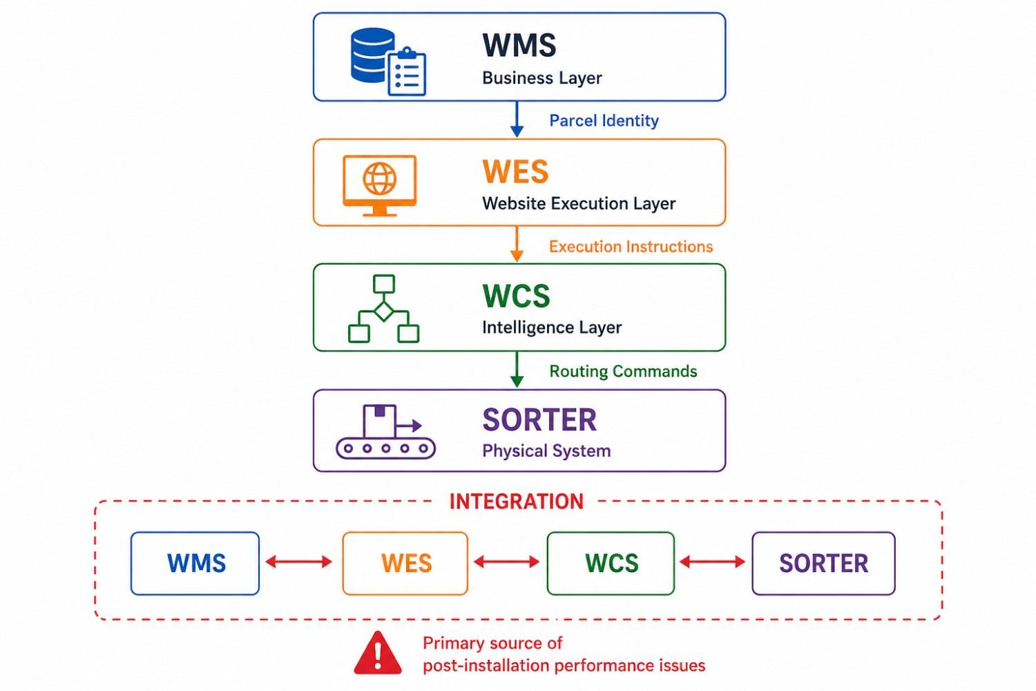
The WCS (Warehouse Control System) is the intelligence layer that tells it what to do with each parcel.
The WMS (Warehouse Management System) is the business layer that tells the WCS what each parcel is.
The integration between these three layers is where the majority of post-installation performance problems originate, and it is the aspect of the procurement process that receives the least scrutiny.
The core handshake works as follows:
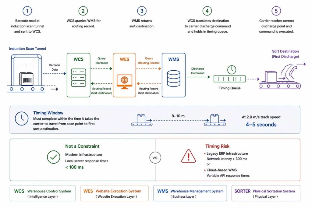
As each parcel passes through the induction scan tunnel, the barcode is read and transmitted to the WCS.
The WCS queries the WMS for the routing record associated with that barcode.
-Add a WES Section here-
The WMS returns the sort destination.
The WCS translates that destination into a carrier discharge command and holds it in a timing queue until the carrier reaches the correct discharge point.
This sequence must complete within the time it takes the carrier to travel from the scan point to the first sort destination; at 2.0 m/s track speed and a typical scan-to-first-chute distance of 8–10 metres, that window is approximately 4–5 seconds.
For a WMS running on modern infrastructure with local server response times of under 100 milliseconds, this is not a constraint.
For a WMS running on legacy ERP infrastructure with network latency above 300 milliseconds, or a cloud-based WMS with variable API response times, the timing window becomes a risk.
The practical due diligence steps before installation:
Conduct a WMS API response time audit under simulated peak load, not idle conditions.
Query the WMS at the rate your target PPH requires (at 6,500 PPH, that is approximately 1.8 barcode queries per second) and measure the p95 response latency.
If p95 exceeds 500 milliseconds, the WCS integration requires a local caching layer.
Define the no-read exception protocol explicitly before commissioning.
Every sorter integration needs a documented answer to the question: what happens when the scan tunnel cannot read the barcode?
The three standard approaches are: divert to a manual exception station, re-induct through a secondary scan point, or hold in a buffer loop.
Each has different throughput implications and different space requirements. This decision needs to be made before the system is installed, not after.
Ensure seamless field-level mapping across your tech stack.
Orders flow from the WMS (which thinks in SKU IDs, order numbers, and shipment references) down to the WES.
The WES acts as the dynamic decision engine, breaking down those business objects into optimized task sequences, pick paths, and container IDs.
From there, the WES feeds the WCS, which operates in real-time machine signals—carrier/license plate IDs, scanner reads, and divert codes.
Bridging these data schemas requires custom translation layers between all three systems.
Always budget appropriately for this custom integration work in both your timeline and project cost.
Which System for Which Operation: A Comparison Table
| Evaluation Attribute | Linear cross-belt Sorter | Loop cross-belt Sorter | Narrow Belt / Shoe Sorter |
|---|---|---|---|
| Throughput Limits (PPH) | 5,000–15,000+ PPH under sustained load with automated induction | 10,000–30,000+ PPH; optimised for mega-hub scale with continuous loop flow | 5,000–9,000 PPH; throughput ceiling is hard and cannot be extended without full replacement |
| Fragile / Deformable Item Handling | High, positive mechanical discharge handles polybags, flyers, and fragile items with calibrated belt timing | High, same cross-belt mechanism; comparable handling capability at higher speed | Low to moderate, friction-based divert mechanism risks polybag skew and fragile item damage at speed |
| Footprint Flexibility | High, straight-track geometry fits brownfield bays, column-constrained floors, and non-standard layouts without structural modification | Low, closed-loop geometry requires large radius turns; difficult to retrofit in constrained existing facilities | Moderate, compact unit but sort destination count is limited; floor area per destination is higher than cross-belt |
| CAPEX Inflection Point | Mid-range; cost-effective for operations between 4,000–12,000 PPH where loop system CAPEX is not justified | High; economically viable only at sustained volumes above 15,000–20,000 PPH where the throughput density justifies the investment | High initial CAPEX; becomes uneconomical when throughput requirements exceed the system’s ceiling and full replacement is required |
| Scalability | High, modular carrier segments can be added to extend track length, and destination count post-installation without full rebuilds | Low, loop architecture is largely fixed at installation; expanding sort destination count requires significant line modification | None; the system cannot be scaled beyond its initial design specification |
Enter Quinta: An Engineering-First Integration Approach

Quinta is not just a sorter manufacturer. That distinction is worth stating directly, because it determines the nature of what you are buying when you engage with us.
Quinta is a system integrator.
When a client brings a sortation requirement, our team begins with a facility audit, floor geometry, column grid, existing WMS platform, parcel mix profile, carrier dock schedule, and peak throughput requirement before a single component is specified.
The system that gets installed is configured for that specific operation, sourcing the appropriate components from a network of qualified global technology partners based on what the engineering requirement actually demands.
Brownfield capability is where this model delivers its most immediate value.
The majority of high-growth warehousing operations are not building new facilities around their automation requirements.
They are retrofitting automation into existing spaces that were not designed for it, spaces with fixed ceiling heights, irregular column spacing, existing mezzanine structures, and floor loads that constrain equipment weight.
Quinta’s linear cross-belt sorter deployments are specifically designed for this environment.
The straight-track architecture and modular installation approach allow the system to be installed in phases, working around operational continuity requirements, without the structural modification costs that loop configurations typically demand in brownfield settings.
Modular scalability addresses the second constraint that most growing operations face: the uncertainty of future volume.
Committing to a system sized for your projected volume in three years means over-investing today.
Quinta’s carrier segment architecture allows the system to start at the throughput your current operation requires and scale incrementally: additional carrier segments, additional sort destinations, additional induction points, as volume grows.
Each expansion is an addition to the existing system, not a replacement of it.
Support model: Quinta operates from its headquarters in Bengaluru with reach across India and internationally.
In the event of a system issue, the protocol is: contact the Quinta team via phone or email, submit a documented video of the fault condition, and our engineering team initiates diagnosis and coordinates with the relevant component manufacturer to dispatch the appropriate technical resource.
This model ensures that every fault is correctly diagnosed before a technician is deployed, eliminating the delays that come from on-site visits that arrive without the right parts or expertise.
For operations outside India, the same diagnostic-first protocol applies, with manufacturer technical support coordinated through Quinta’s support network.
If you are at the stage of evaluating whether a linear cross-belt sorter is the right next step for your operation, the most productive starting point is a direct conversation with our team.
We will work through your throughput requirements, floor constraints, parcel mix, and integration environment, and give you an honest assessment of what the right system looks like before any commercial conversation begins.

